


一、The Role of Pin Contacts in Data Cables
Pin contacts are the core interface components responsible for signal and power transmission in data cables, and their design directly affects:
⚡Charging Efficiency and Current Carrying Capacity
📶 Data Transmission Stability and Speed
🔁 Insertion and Removal Life Cycle and Contact Reliability
🔥 Contact Resistance and Heat Generation Control
二、Structural Differences of Pin Contacts in Common Connector Types
1️⃣ USB Type-A / Type-C Connectors
Type-A(USB 2.0)
4 Pin Structure
VBUS (Power Supply)
D+
D-
GND
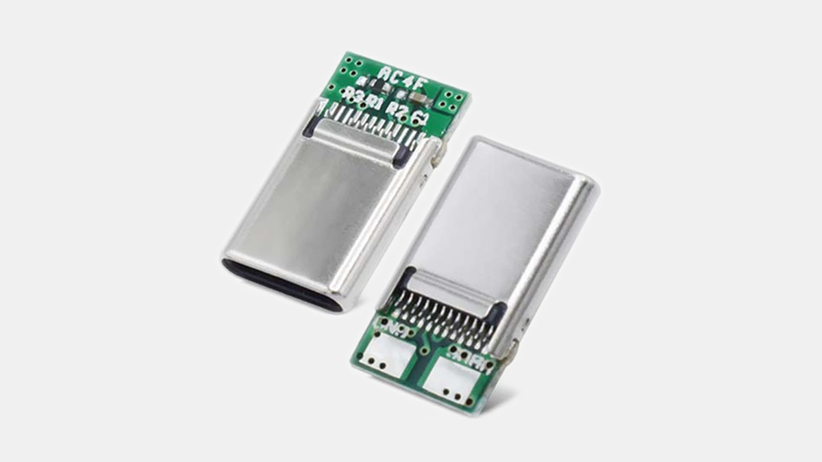
Type-C(USB-C)
24 Pin Symmetrical Design
Supports Reversible Insertion
Functions Include:
Power (VBUS / GND)
High-Speed Differential Pair
CC Channel
SBU Auxiliary Channel
👉 Key Points of High-Power Fast Charging Cables:
VBUS and GND typically use multiple pins in parallel to increase current carrying capacity and reduce localized heating.
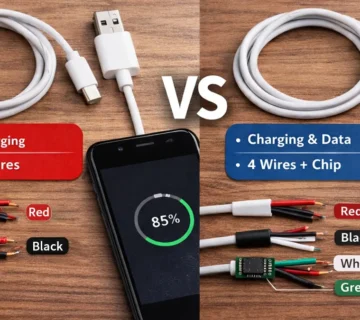
2️⃣Lightning Connector (Apple)
8 Pin Dual-Sided Contact Design
The connector internally uses an IC chip for function identification.
Soldering of Pin Contacts to FPC or PCB
三、Selection of Pin Contact Materials (Key Parameters)
1️⃣ Base Material
| Material | Characteristics | Application |
|---|---|---|
| Phosphor Bronze | High elasticity, fatigue-resistant | Mainstream choice |
| Brass | Low cost, good conductivity | Entry-level |
| Beryllium Copper | Excellent elasticity, long lifespan | High-end industrial grade |
2️⃣ Surface Plating
The plating has a significant impact on the lifespan and contact performance.
| Plating | Advantages | 一般的な厚さ |
|---|---|---|
| Gold (Au) | Low contact resistance, corrosion-resistant | 0.1–1.0 μm |
| Nickel (Ni) | Basic protective layer | 1–2 μm |
| Tin (Sn) | Low cost | Entry-level products |
👉 Standard Practice:
Nickel Underlayer + Gold Surface (Ni + Au) Composite Plating Structure
四、Key Points in Pin Contact Structural Design
1️⃣ Contact Type
Spring Contact ✅ 主流
Rigid Contact ❌ Not suitable for frequent plugging/unplugging
The spring contact structure provides stable contact pressure, reducing the risk of poor contact.
2️⃣ Contact Force
Too low → Unstable contact
Too high → Difficult to plug/unplug, accelerated wear
📌 Typical Industry Control Range:
0.4 – 1.2 N / Pin
3️⃣ Pin Arrangement and Pitch
High-speed signal PIN require matched length and uniform spacing.
Strictly control impedance consistency.
Prevent crosstalk and signal reflection.
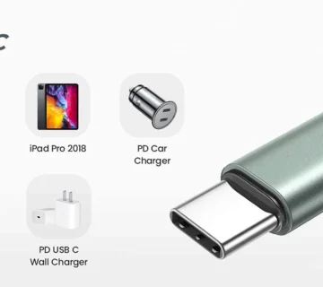
五、High-Power Fast-Charging Dedicated Pin Design
For 60W / 100W / 240W (USB PD)
Key optimization points include:
🔌 Power PINs widened or paralleled
🔥 Reduce contact resistance (≤30 mΩ)
🧠Built-in E-Marker Chip (Type-C)
🛡 Increased gold plating thickness
六、PIN Connection and Internal Wiring
| Method | Characteristics | Application |
|---|---|---|
| Direct soldering | Low cost | Type-A |
| FPC Flexible Cable | High density | Type-C |
| PCB Soldering | High stability | High-end cables |
七、Reliability and Lifetime Testing
Professional manufacturers typically perform the following tests:
Insertion/Withdrawal Life Test (≥10,000 cycles)
Contact Resistance Variation Test
High-Temperature and High-Humidity Aging
High-Current Electrical Aging
No comment